No products in the cart.
Sensors
Pololu VL53L0X Time-of-Flight Distance Sensor Carrier with Voltage Regulator
Availability:
4 in stock
This sensor is a carrier/breakout board for ST’s VL53L0X laser-ranging sensor, which measures the range to a target object up to 2 m away. The VL53L0X uses time-of-flight measurements of infrared pulses for ranging, allowing it to give accurate results independent of the target’s color and surface. Distance measurements can be read through a digital I²C interface. The board has a 2.8 V linear regulator and integrated level-shifters that allow it to work over an input voltage range of 2.6 V to 5.5 V, and the 0.1″ pin spacing makes it easy to use with standard solderless breadboards and 0.1″ perfboards.
$7.00
4 in stock
Specifications
- Dimensions: 0.5″ × 0.7″ × 0.085″ (13 mm × 18 mm × 2 mm)
- Weight without header pins: 0.5 g (0.02 oz)
- Operating voltage: 2.6 V to 5.5 V
- Supply current: 10 mA (typical average during active ranging)
- Varies with configuration, target, and environment. Peak current can reach 40 mA.
- Output format (I²C): 16-bit distance reading (in millimeters)
- Distance measuring range: up to 2 m (6.6 ft); see the graph at the right for typical ranging performance.
- Effective range depends on configuration, target, and environment.
- The datasheet does not specify a minimum range, but in our experience, the effective limit is about 3 cm.
Pinout
| PIN | Description |
|---|---|
| VDD | Regulated 2.8 V output. Almost 150 mA is available to power external components. (If you want to bypass the internal regulator, you can instead use this pin as a 2.8 V input with VIN disconnected.) |
| VIN | This is the main 2.6 V to 5.5 V power supply connection. The SCL and SDA level shifters pull the I²C lines high to this level. |
| GND | The ground (0 V) connection for your power supply. Your I²C control source must also share a common ground with this board. |
| SDA | Level-shifted I²C data line: HIGH is VIN, LOW is 0 V |
| SCL | Level-shifted I²C clock line: HIGH is VIN, LOW is 0 V |
| XSHUT | This pin is an active-low shutdown input; the board pulls it up to VDD to enable the sensor by default. Driving this pin low puts the sensor into hardware standby. This input is not level-shifted. |
| GPIO1 | Programmable interrupt output (VDD logic level). This output is not level-shifted. |
Schematic diagram
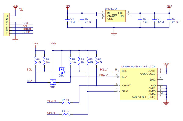 |
The above schematic shows the additional components the carrier board incorporates to make the VL53L0 easier to use, including the voltage regulator that allows the board to be powered from a 2.6 V to 5.5 V supply and the level-shifter circuit that allows for I²C communication at the same logic voltage level as VIN. This schematic is also available as a downloadable PDF (108k pdf).
I²C communication
The VL53L0X can be configured and its distance readings can be queried through the I²C bus. Level shifters on the I²C clock (SCL) and data (SDA) lines enable I²C communication with microcontrollers operating at the same voltage as VIN (2.6 V to 5.5 V). A detailed explanation of the I²C interface on the VL53L0X can be found in its datasheet (1MB pdf), and more detailed information about I²C in general can be found in NXP’s I²C-bus specification (1MB pdf).
The sensor’s 7-bit slave address defaults to 0101001b on power-up. It can be changed to any other value by writing one of the device configuration registers, but the new address only applies until the sensor is reset or powered off. ST provides an application note (196k pdf) that describes how to use multiple VL53L0X sensors on the same I²C bus by individually bringing each sensor out of reset and assigning it a unique address.
The I²C interface on the VL53L0X is compliant with the I²C fast mode (400 kHz) standard. In our tests of the board, we were able to communicate with the chip at clock frequencies up to 400 kHz; higher frequencies might work but were not tested.
Sensor configuration and control
In contrast with the information available for many other devices, ST has not publicly released a register map and descriptions or other documentation about configuring and controlling the VL53L0X. Instead, communication with the sensor is intended to be done through ST’s VL53L0X API (STSW-IMG005), a set of C functions that take care of the low-level interfacing. To use the VL53L0X, you can customize the API to run on a host platform of your choice using the information in the API documentation. Alternatively, it is possible to use the API source code as a guide for your own implementation.
Sample Code
We have written a basic Arduino library for the VL53L0X, which can be used as an alternative to ST’s official API for interfacing this sensor with an Arduino or Arduino-compatible controller. The library makes it simple to configure the VL53L0X and read the distance data through I²C. It also includes example sketches that show you how to use the library.
Based on 0 reviews
Only logged in customers who have purchased this product may leave a review.


There are no reviews yet.